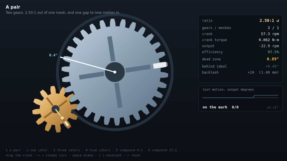
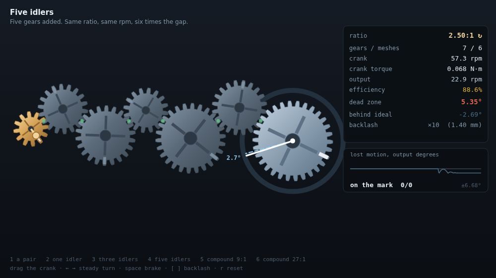
Put a third gear between two others and something strange happens: the output reverses, and its speed does not change at all. Not approximately. The gear you added is called an idler, and the name is the whole joke — it turns, it meshes, it is load-bearing in the literal sense, and it contributes nothing to the ratio. Two gears, or seven, the crank still turns 2.5 times for every turn of the far end.
That is the fact everyone who has taken a clock apart half-remembers. What nobody says out loud is what the free gears cost, so I built the train as physics rather than arithmetic — discs with real inertia, meshes that are springs with a gap in the middle of them — and went looking for the bill.
Idlers are free, and here is the invoice
Same 12-tooth crank, same 30-tooth output gear, idlers of assorted sizes dropped in between. Driven at 60 rpm against a 0.2 N·m load:
| idlers | gears | meshes | ratio | output rpm @ 60 | crank torque | efficiency | lost motion | predicted |
|---|---|---|---|---|---|---|---|---|
| 0 | 2 | 1 | 2.5000:1 | 24.00 | 0.0819 N·m | 97.7% | 0.093° | 0.089° |
| 1 | 3 | 2 | 2.5000:1 | 24.00 | 0.0834 N·m | 95.9% | 0.185° | 0.178° |
| 2 | 4 | 3 | 2.5000:1 | 24.00 | 0.0850 N·m | 94.2% | 0.279° | 0.267° |
| 3 | 5 | 4 | 2.5000:1 | 24.00 | 0.0866 N·m | 92.4% | 0.372° | 0.357° |
| 4 | 6 | 5 | 2.5000:1 | 24.00 | 0.0881 N·m | 90.8% | 0.467° | 0.446° |
| 5 | 7 | 6 | 2.5000:1 | 24.00 | 0.0898 N·m | 89.1% | 0.559° | 0.535° |
The ratio column is not rounded to look tidy — it is 2.5000 six times, and the output turns at 24.00 rpm six times, because the middle gears cancel telescopically: 12/18 × 18/22 × 22/16 × … × 26/30 leaves 12/30 standing and nothing else. Every idler is a term that divides itself out.
The last three columns are what it costs to keep saying that. The first mesh takes 2.3% off the top and each idler after it takes another 1.8 points, so by the fifth the crank is pushing 9.6% harder to deliver the same 0.2 N·m at the far end. And lost motion — the angle you can turn the crank, after a reversal, before the output moves at all — grows by 0.093° per mesh, dead straight, from 0.09° to 0.56°.
That last column is the honest part of the experiment. lostMotionDeg()
predicts the dead zone from the geometry alone; the measurement creeps the
train forward until every flank is loaded, then creeps it back and watches for
the output to move. They agree within 4%, which is how I know the sim is
measuring backlash and not measuring me.
Where you put it matters more than how many
This is the one I did not expect to be so large. Two-stage compound reduction, 12:36 then 12:36, exactly 9:1. Add one 20-tooth idler — the same part, the same tooth count, the same 9:1 either way — and the only variable is which side of the reduction it sits on:
| train | ratio | meshes | efficiency | lost motion | predicted |
|---|---|---|---|---|---|
| no idler | 9.000:1 | 2 | 94.5% | 0.085° | 0.099° |
| idler on the fast side | 9.000:1 | 3 | 92.2% | 0.103° | 0.124° |
| idler on the slow side | 9.000:1 | 3 | 92.8% | 0.175° | 0.173° |
On the crank side the idler adds 0.018° at the output. On the far side, the identical gear adds 0.090° — five times as much, for the same part in the same train doing the same job.
The reason is that a reduction divides backlash the same way it divides speed. A gap opened upstream of a 3:1 stage arrives at the output a third as wide; a gap opened downstream of everything arrives at full size. So slop belongs where the shafts are spinning fastest, which is the exact opposite of where intuition puts it — you want the sloppy, cheap, fast-turning gears near the motor and the tight expensive ones near the thing that has to be accurate. That is the rule of thumb machine designers state as a preference; here it is just arithmetic, and it has a number on it.
The only thing that actually changes a ratio
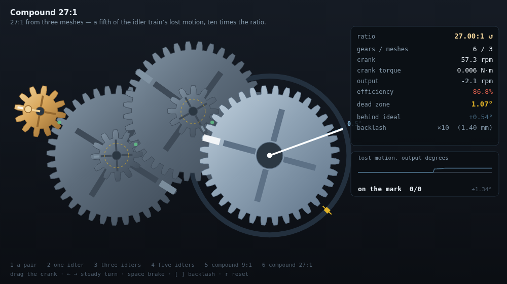
An idler cannot change the ratio because it drives with the same teeth it was driven by. Put two gears on one shaft — a compound — and it drives with a different tooth count than it received, and the term stops cancelling. That is the entire mechanism, and it is worth what six idlers are not:
| train | gears | meshes | ratio | output rpm @ 60 | crank torque | efficiency | lost motion |
|---|---|---|---|---|---|---|---|
| pair, 12:30 | 2 | 1 | 2.500:1 | 24.00 | 0.0819 N·m | 97.7% | 0.093° |
| + 5 idlers | 7 | 6 | 2.500:1 | 24.00 | 0.0898 N·m | 89.1% | 0.559° |
| compound, 2 stages | 4 | 2 | 9.000:1 | 6.67 | 0.0235 N·m | 94.5% | 0.085° |
| compound, 3 stages | 6 | 3 | 27.000:1 | 2.22 | 0.0084 N·m | 88.7% | 0.105° |
Compare the last two rows against the second. The 27:1 train has half the meshes, ten times the ratio, and a fifth the lost motion of the idler train — 0.105° against 0.559° — and it gets there with one fewer gear. Its backlash is small for the reason the previous table just established: two of its three gaps sit upstream of a reduction that shrinks them on the way out.
What the crank feels
Bolt a 20 g·m² flywheel to the output — as much rotational inertia as the largest gear in the train — and ask how hard the crank is to accelerate:
| train | ratio | crank alone | felt at the crank | predicted | flywheel share |
|---|---|---|---|---|---|
| direct, 1:1 | 1.00:1 | 3.95 g·m² | 28.52 g·m² | 27.90 g·m² | 20.00 g·m² |
| 2.5:1 reduction | 2.50:1 | 0.25 g·m² | 5.06 g·m² | 4.99 g·m² | 3.20 g·m² |
| 9:1 compound | 9.00:1 | 0.25 g·m² | 3.05 g·m² | 2.99 g·m² | 0.25 g·m² |
| 27:1 compound | 27.00:1 | 0.25 g·m² | 2.85 g·m² | 2.80 g·m² | 0.03 g·m² |
Inertia reflects through a ratio squared. Through 27:1 the flywheel arrives at the crank as 0.03 g·m² — a 729th of itself, one percent of the intermediate gears, and completely undetectable by hand. Past about 9:1 the flywheel has stopped existing as far as your wrist is concerned and everything you can feel is the gears near the crank. Which is why the last row is lighter than a straight 1:1 and why gearing something down makes it feel not just easier but disconnected.
What you do in the demo
Drag the crank. The brass gear follows your pointer through a hand with finite stiffness, so the train’s weight and drag are in your hand, not just in the panel.
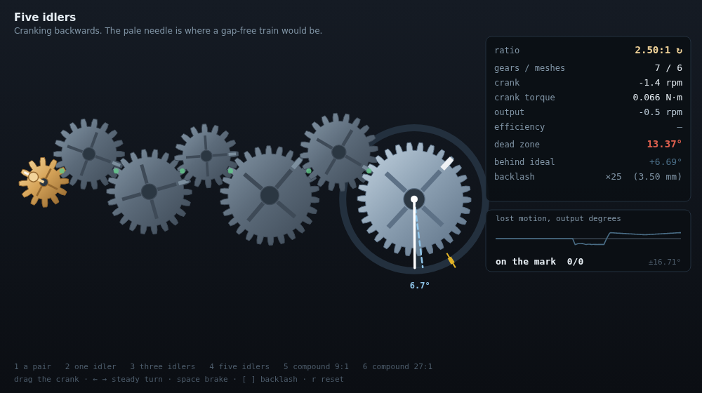
- The dial around the output carries two needles. The white one is the output. The dashed one is where a gap-free train would have put it, integrated from the crank you actually turned, and the wedge between them is the backlash — the only part of a gear train you can see doing nothing.
- Reverse and watch the wedge flip sides. It swings between ±half the dead zone, so the peak-to-peak of the trace at the bottom right is the number in the panel.
- The dots at each mesh are green while a flank is carrying and red while the pair is floating in its own gap, transmitting nothing.
- Land the needle on the mark. Each mark is on the far side of a reversal, so every attempt spends the dead zone. On two gears it is a rounding error; on seven it is the whole game.
1–6walk the trains,[and]scale backlash between ×1 (0.14 mm, the real thing, invisible) and ×25,spaceloads the output,←/→crank steadily,rresets.
The demo runs at ×10 backlash by default, because at ×1 the effect is a tenth of a degree and you would never see it. Every number in the tables above is at ×1.
Reuse
src/geartrain.mjs is framework-free and draws nothing. SI units throughout.
createTrain(spec)—spec.gearsis a list of{ teeth, x, y }(root),{ teeth, mesh: i, angle }(meshed with entryi, placed at that bearing) or{ teeth, on: i }(a second gear on entryi’s shaft — a compound). Centre distances come out of the tooth counts, so a spec cannot describe a train that does not mesh.chain([12, 18, 30])andcompound([[12, 36], [12, 36]])build the two shapes worth having.step(state, dt, { inputTorque | inputOmega, loadTorque })— one step.inputOmegadrives the crank kinematically (a perfectly stiff hand) and reports back what it had to supply asstate.crankTorque;inputTorqueis the torque-driven version the demo uses.idealRatio(state)— signed output turns per input turn.speedFactors()gives it for every body.lostMotionDeg(state)— the dead zone at the output, from geometry.measureSteady,measureLostMotion,measureReflectedInertia— the three experiments above, headless.scripts/measure.mjsreproduces every table in about 200 ms.- Gear rendering is the demo’s business, but
body.rings[i].phaseis set at build time so drawn teeth interleave correctly on the line of centres.
Gotchas
-
The efficiency numbers are a model, not a discovery. Tooth loss here is lumped: sliding runs at
MESH.slideof the pitch-line speed with a friction coefficientMESH.mu, which lands at ~2.3% per mesh — the right ballpark for a spur pair, but it is a number I put in, not one that fell out. What did fall out is that it multiplies, and that the crank torque required rises with it while the ratio does not move. Treat the per-mesh figure as an assumption and the per-train consequence as the result. -
Backlash is the model’s whole point and it is one number. A mesh is a spring that only pushes once
|s − s₀|exceeds half the lash, wheres = r_a·θ_a + r_b·θ_bis the mesh coordinate. There is no separate drive/coast flank stiffness, no tooth profile, no variable mesh stiffness through a tooth cycle. Real backlash also breathes with temperature and centre distance; this one does not. -
Trains start mid-gap.
s₀is captured at build time with every mesh centred in its dead band, so a freshly loaded train sits half a gap from either flank. That is why the demo’s behind ideal readout swings ±half the dead zone rather than 0 to the full value. -
The measured dead zone runs under the prediction on the fast side.
lostMotionDegadds up every gap as though it were fully traversed; in the sim an idler with real inertia coasts and closes part of its own gap on the way, so the measurement comes in 4% low on a chain and up to 17% low when the extra gap is upstream of a reduction. The slow-side case, where the gap is the last thing before the output, matches to within 1%. The disagreement is the interesting part: it is inertia, not geometry. -
Teeth are cosmetic. The drawn tooth is a trapezoid, not an involute, and contact is modelled at the pitch point along a fixed line of action. This buys the whole piece — one degree of freedom per gear, no contact search — and costs it anything that depends on profile: pressure angle, undercut, contact ratio, and the mesh-stiffness ripple that makes real gears whine.
-
The load has no stiction.
softSignsmooths the Coulomb terms over ±0.05 rad/s so the solver does not chatter, which means a stopped output can creep instead of holding. A real machine’s stiction adds to lost motion; the numbers here are the optimistic end. -
Two gears on one shaft are drawn in one plane, so a compound train overlaps itself on screen the way it never would on a bench. The dashed amber ring marks a shared shaft.
-
Timestep. The mesh spring is stiff (6×10⁵ N/m), so this is the table that says the results are the model’s and not the integrator’s:
dt ratio, 3 idlers efficiency lost motion 1/5000 2.5000:1 92.37% 0.372° 1/10000 2.5000:1 92.37% 0.372° 1/20000 2.5000:1 92.37% 0.372° 1/40000 2.5000:1 92.37% 0.372° Eight times the resolution moves nothing at four significant figures. The demo runs at 1/8000 with substepping.
-
demo/bundles its own copy of the module (self-contained by contract). If you touchsrc/, re-copy it intodemo/.