






A disc brake is a clamp. You squeeze, it rubs, the rubbing is the braking, and the harder you squeeze the more you get. It is the machine you would design if someone described the problem to you over the phone.
A drum brake is not that. A drum brake is two curved shoes inside a spinning iron pot, and the drag does not only slow the drum — it also pushes the shoe, and where it pushes the shoe depends on which end of the shoe is bolted down. One of them gets pushed harder onto the drum by its own friction. The other gets peeled off by exactly the same force.
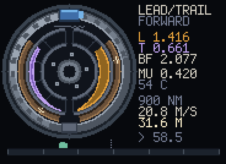
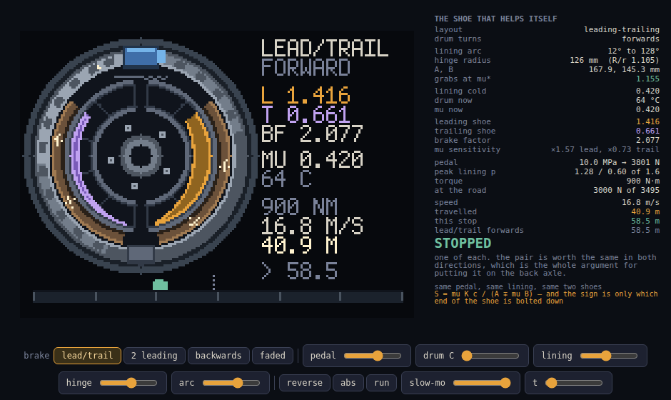
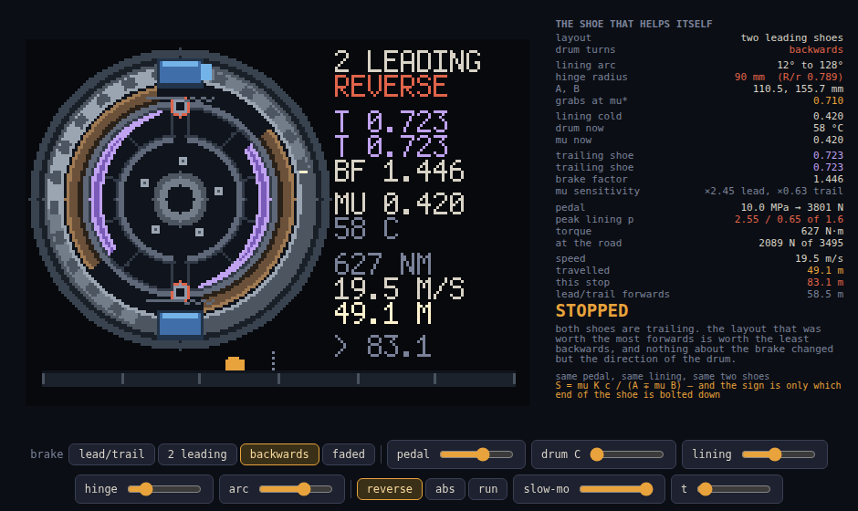
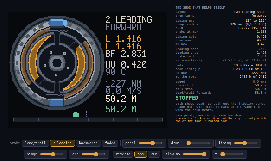
The sprite is one rear brake with the drum drawn transparent: two shoes, a wheel cylinder, an anchor pin, the lining pressure drawn on each shoe as the lobe it really is, and a road strip along the bottom with the car on it.
The shoe that helps itself
Hinge a shoe at one end, push it at the other. Now turn the drum.
If the drum’s surface sweeps from the pushed end toward the hinge, friction drags the shoe deeper in, and the deeper it goes the harder it is pressed, and the harder it is pressed the more it drags. That is a leading shoe, and it is self-energising. Turn the drum the other way and the same friction, on the same shoe, tries to lift it off its own hinge. That is a trailing shoe.
Nothing has changed except the direction of the drum.
How much, exactly
Take the standard long-shoe analysis: the lining presses with p = pa sin θ ⁄ sin θa over its arc, θ measured round from the hinge line. Drum bore radius r, hinge at radius R, lining from θ₁ to θ₂, actuating force applied a perpendicular distance c from the hinge. Two integrals fall out, and they are the whole of it:
K = cos θ₁ − cos θ₂                       J = sin²θ₂ − sin²θ₁

A = R·K − (r/2)·J        ← moment of the pressure about the hinge
B = r·K − (R/2)·J        ← moment of the friction about the hinge
The friction moment helps a leading shoe and fights a trailing one, so the force the cylinder has to supply is proportional to A − μB for one and A + μB for the other, while the torque they produce is the same formula for both. Divide one by the other and the whole brake collapses to a single dimensionless number per shoe — the shoe factor, torque out per unit of push, per drum radius:
S = μ K c / (A ∓ μB) minus leading, plus trailingOn this brake — r = 114 mm, R = 126 mm, lining 12° to 128°, c = 226 mm — that is A = 167.889 mm and B = 145.297 mm, and at a cold μ of 0.42:
| shoe factor | peak lining pressure | |
|---|---|---|
| leading shoe | 1.416 | 1.282 N/mm² |
| trailing shoe | 0.661 | 0.599 N/mm² |
| ratio | 2.142 | 2.142 |
Two identical shoes. One cylinder. One pressure. One of them does 2.14 times the work of the other, and the lining, the friction coefficient and the width of the shoe are not what decides it — they cancel out of the ratio entirely.
That ratio is the picture. The two pressure lobes in the sprite are drawn at p = pa sin θ ⁄ sin θa to one fixed scale, and because the same push has to be reacted by different pressure, the lobes come out in exactly the shoe-factor ratio. The orange one is the leading shoe. The violet one is the shoe that is only being pushed. You are not looking at an illustration of the number; you are looking at the number.
It is also why the two linings do not wear out together. They left the factory identical and the leading one is being pressed twice as hard, every stop, forever.
The zero, and the reason you can never reach it
Look at A − μB again. It has a zero in it.
Set A − μB = 0 and the cylinder needs no force at all: the shoe drags itself on and locks the wheel with your foot nowhere near the pedal. The threshold is
μ* = A / Band there is no lining in it. No pressure, no width, no temperature. It is pure geometry — and this is the part worth the sprite.
Write x = R/r. The two integrals share their terms, so
μ* = (x·K − J/2) / (K − x·J/2)At x = 1 the numerator and denominator are the same expression, so μ = 1 exactly*, whatever the lining arc is. Above x = 1 it rises monotonically (K, J > 0, and K − xJ/2 stays positive for any x short of 2K/J = 5.52).
So a hinged shoe grabs only if the hinge pin is inside the bore of the drum. There is a drum there. That is what a drum is.
On this geometry μ* = 1.1555, and the best lining anyone has ever bolted to a shoe is not close. Drag the hinge slider in the demo and watch it fall: 1.156 at R = 126, 1.000 at R = 114, 0.710 at R = 90 — where the pin is drawn in red because it is now standing in the middle of the iron.
Self-locking drum brakes are real, and this is why none of them is this one: they get there by chaining shoes together, not by hinging one cleverly.
What self-energisation actually costs
Take the log derivative of S and the amplification is one line:
d ln S / d ln μ = 1 / (1 ∓ μB/A)which on this brake is ×1.571 for the leading shoe and ×0.733 for the trailing one. The shoe that hands you the free torque is the shoe that hands it back fastest, and the shoe that looked weak is the one holding the brake’s behaviour together.
Which sets up the fourth loop. Hold 25 m/s down a 9% grade for six minutes on the brakes and 8.3 kW goes into a 6.5 kg lump of cast iron; after six minutes it is at 487 °C and still climbing, and the lining that was worth 0.42 is worth 0.251. That is a 40% loss of μ. The leading shoe gives back 51% of its factor. The stop, on the same pedal, goes from 58.5 m to 111.5 m — nearly double, with the pedal in exactly the place it was at the top of the pass, which is the part that kills people.
And the brake that is better is worse
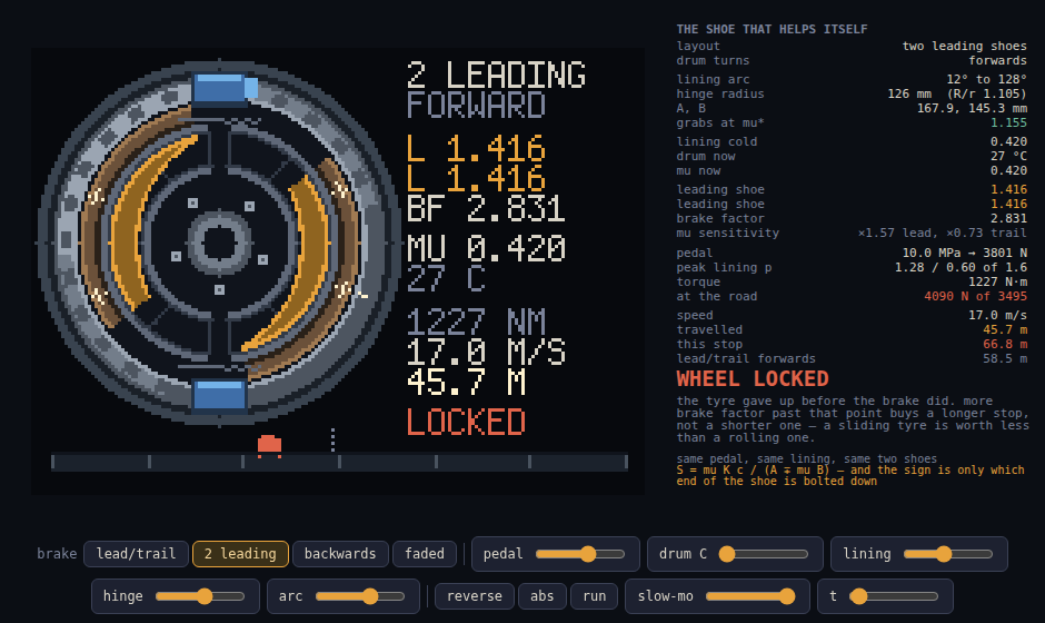
If a leading shoe is worth 2.14 trailing shoes, build both of them leading. That is the two-leading-shoe brake: two single-acting cylinders diagonally opposite, each one’s body serving as the abutment for the other shoe. The sprite draws it — the anchor block at the bottom is gone and there is a second cylinder in its place.
It has two bills, and the sprite is the two loops that pay them.
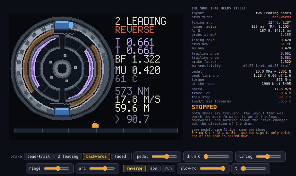
One: it only works one way round. Roll backwards and both shoes trail. 2.831 becomes 1.322, a 53% loss, on a car that stops beautifully forwards. A leading-trailing brake has one of each, so its total is identical in both directions — which is the entire argument for putting it on the back axle of almost every car that ever had drums there, and for why the handbrake works on a hill you are rolling down.
Two: past a point, more brake factor is not more braking. The tyre on this corner can carry 3495 N and not one newton more. At 10 MPa of line pressure:
| brake factor | torque | at the road | stop | |
|---|---|---|---|---|
| leading + trailing, forwards | 2.077 | 900 N·m | 3000 N | 58.5 m |
| two leading, forwards | 2.831 | 1227 N·m | 4089 N — over | 66.8 m, locked |
| two leading, backwards | 1.322 | 573 N·m | 1910 N | 90.7 m |
| leading + trailing at 487 °C | 1.131 | 490 N·m | 1633 N | 111.5 m |
The strong brake stops 8.3 m later than the weak one. It asked the tyre for 4089 N, the tyre gave up at 3495, and a sliding tyre is worth 0.70 where a rolling one was worth 0.95. The 36% more brake factor bought a longer stop.
Hold it at the edge instead — press abs in the demo — and the same brake
stops in 50.2 m. The extra factor was always there. There was just nothing
in 1955 that could spend it.
The loops
| loop | frames | what it is |
|---|---|---|
lead | 8 | leading + trailing, forwards. 1.416 against 0.661, and the lobes to match. |
twin | 6 | two leading shoes, forwards. Locks the wheel and stops 8.3 m later. |
back | 6 | the same brake rolling backwards. Both shoes trail. |
fade | 8 | leading + trailing at the bottom of the descent. 487 °C, and 111.5 m. |
Reuse
source/wrap.mjs is framework-free and has no DOM in it above the drawing
layer. The brake is separable from the sprite:
import { shoeFactor, selfLockMu, integrals, brakeTorque, cfgOf } from './wrap.mjs';

selfLockMu({ r: 114, R: 126, th1: 12, th2: 128 });   // 1.1555 — geometry only
shoeFactor(0.42, true);                              // 1.4157 leading
shoeFactor(0.42, false);                             // 0.6609 trailing
brakeTorque(cfgOf({ layout: '2ls' }), 0.42, 10);     // 1227 N·m
simulate(cfg, t) integrates the stop at 2 ms: pressure ramp, lining fade from
drum temperature, tyre ceiling with latching lock-up, and the drum’s own
thermal balance. stopTest(cfg) runs it to the end and reports.
Everything drawn is derived. validateGeometry() re-proves the load-bearing
claims on every render — that μ* is exactly 1 when R = r, that it rises
monotonically and never dips below 1 with the hinge outside the bore, that the
drawn lobe ratio equals the shoe-factor ratio to machine precision, and that
leading-trailing is direction-blind while two-leading is not.
node source/render.mjs regenerates every PNG and reprints every number in
this file. node scripts/screenshot-demo.mjs boots the demo in a real browser,
photographs it, and checks 28 assertions against it — including two that count
pixels out of the drawing rather than trusting the model.
Gotchas
- The shoe arcs are drawn about the drum axis, not about each shoe’s own hinge. Real shoes are very slightly eccentric to the bore; at 0.377 px/mm the difference is under a pixel, and the pressure lobe — which is the thing that matters — is computed from the real hinge geometry either way.
shoeFactorreturnsInfinitypast μ*, and everything downstream is written to survive it: the torque is infinite, the wheel locks on the first step, and ABS is explicitly not allowed to modulate it, because a shoe that is dragging itself on is not listening to the line pressure.- The lobe scale is fixed at the lining’s 1.6 N/mm² rating rather than
normalised per frame, so a lobe in the
fadeloop is honestly smaller than the same lobe inlead. Normalising would have made the fade invisible, which is the one thing the fade loop is for.