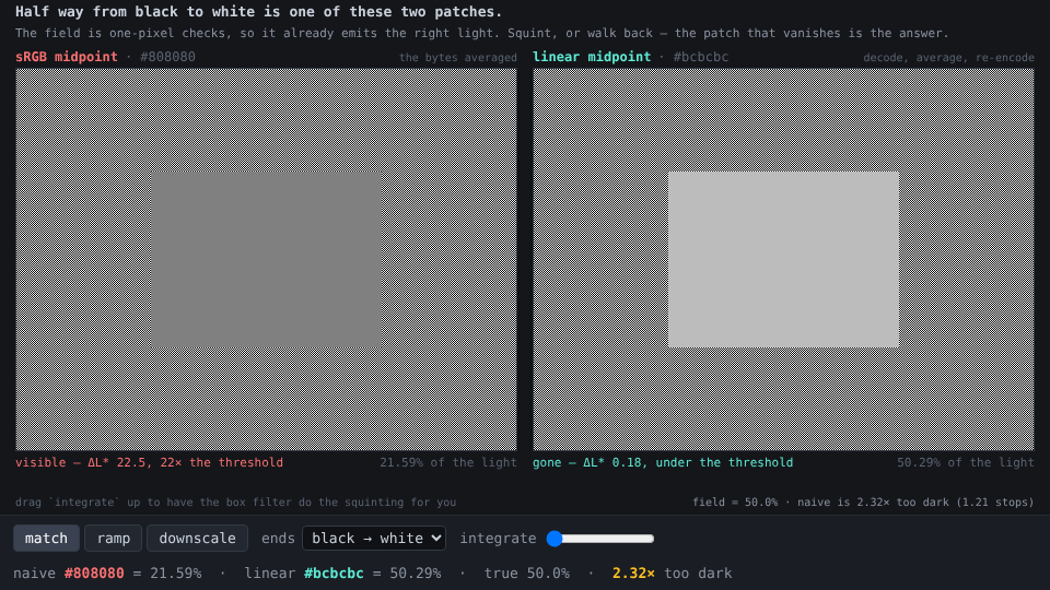
Ask for the colour half way between black and white and almost everything answers 128. It is the midpoint of the byte, and the byte is what the question was about. It is also 2.32× too dark, and the demo does not argue the point — it puts the answer next to a surface that is already emitting the right amount of light and lets you look.
That surface is a checkerboard of one-pixel black and white cells. Nobody
decoded anything to make it; half the pixels are on and the light from them
adds, which is the one operation in this whole subject that cannot be done in
the wrong space. So a patch laid on that field is correct exactly when it
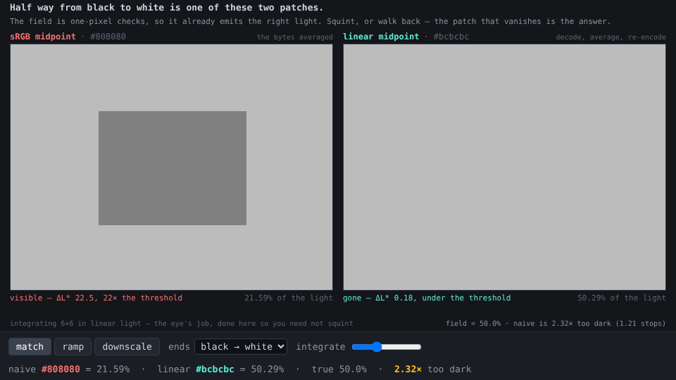
disappears. Squint, lean back, or turn the integrate slider up and let a box
filter do the squinting.
| byte | light emitted | ΔL* vs the field | |
|---|---|---|---|
| sRGB midpoint | 128 | 21.59% | 22.5 |
| linear midpoint | 188 | 50.29% | 0.18 |
| the field itself | — | 50.00% | — |
ΔL* is CIE lightness difference, where 1 is roughly the smallest difference anyone can see. The naive answer is off by twenty-two of them. It is not a subtlety that only shows up in a side-by-side; it is one of the largest errors you can make while every individual pixel is still a legal colour.
188, and the two numbers that make it
sRGB stores a number that is roughly the 1/2.2 power of the light. Inverting it at a half:
linearToSrgb(0.5) × 255 = 187.516  →  188
srgbToLinear(128/255)   = 0.21586
Those are the whole creation. The second one is the one worth keeping: byte 128 is not half the light, it is 21.6% of it, which is 1.21 stops down. Every pipeline that treats the byte as a quantity — averages it, lerps it, multiplies it by an alpha — is doing arithmetic on the logarithm and reporting the answer as if it were the number.
The 0.29 points by which 188 overshoots are not a flaw in the method. 187.516 is not a byte; 188 is the nearest one, and across the whole ramp the rounding costs at most ΔL* 0.234, a quarter of the threshold. The 8-bit grid is the floor here, not the maths.
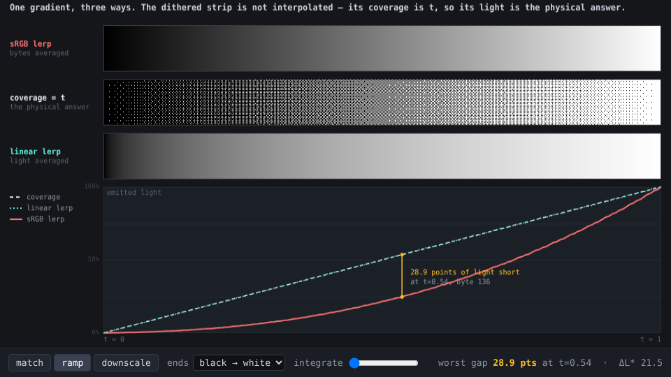
The whole ramp is wrong, and the worst of it is not the middle
Same two endpoints, swept:
| t | naive byte | its light | linear byte | its light | wanted | short by | ΔL* |
|---|---|---|---|---|---|---|---|
| 0.1 | 26 | 1.0% | 89 | 10.0% | 10% | 9.0 | 28.6 |
| 0.2 | 51 | 3.3% | 124 | 20.2% | 20% | 16.7 | 30.6 |
| 0.3 | 77 | 7.4% | 149 | 30.1% | 30% | 22.6 | 28.9 |
| 0.5 | 128 | 21.6% | 188 | 50.3% | 50% | 28.4 | 22.5 |
| 0.535 | 136 | 24.6% | 193 | 53.3% | 53.5% | 28.9 | 21.5 |
| 0.7 | 179 | 45.1% | 218 | 70.1% | 70% | 24.9 | 14.1 |
| 0.9 | 230 | 79.1% | 243 | 89.6% | 90% | 10.9 | 4.7 |
Two different maxima, and they are in different places. The light goes missing fastest just past the middle — 28.9 points at t = 0.535 — because that is where the gap between a curve and its chord is widest. What you can see peaks much earlier, at ΔL* 30.8 at t = 0.194, because the eye spends most of its resolution in the shadows and a deficit down there costs more lightness per point of light. The shadows are where a naive blend looks worst, and the shadows are the part everyone checks last.
The band in between is the real finding: 98.1% of the ramp sits above ΔL* 1. There is no safe region. Only the two endpoints, where the two spaces are forced to agree, are right.
One filter, two spaces
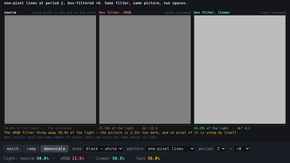
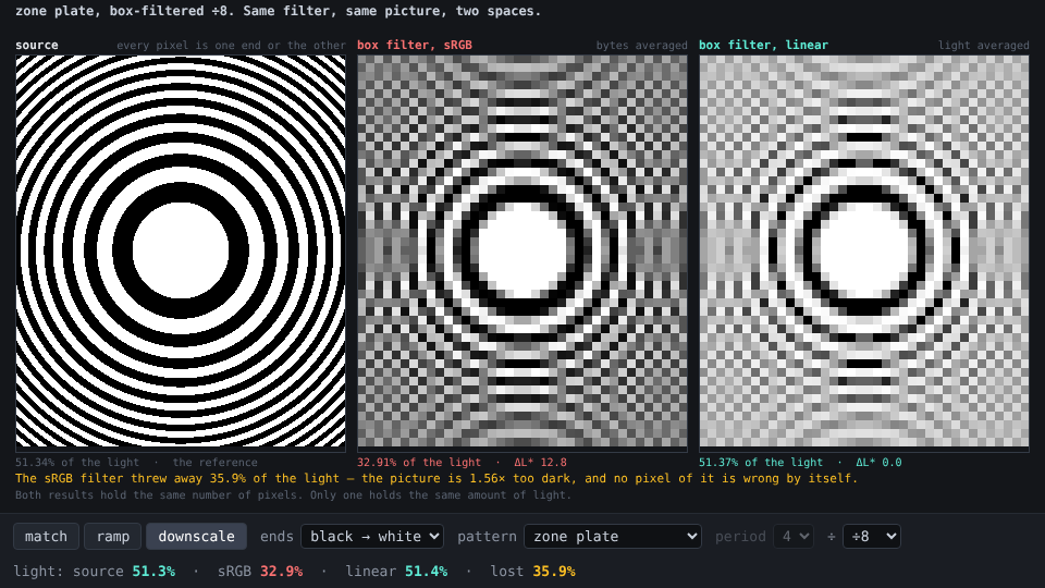
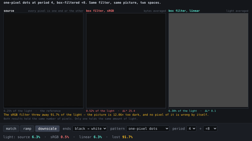
Nothing in the downscale view is interpolated by hand. It is one two-valued picture — every pixel is one endpoint or the other, so there is no midtone to get wrong and any midtone in the result was manufactured by the filter — put through one box filter, run in either space. The mean light is the only number that should survive:
| picture | source | sRGB box | linear box | light thrown away | too dark by |
|---|---|---|---|---|---|
| one-pixel lines, period 2 | 50.00% | 21.59% | 50.29% | 56.8% | 2.32× |
| one-pixel lines, period 4 | 25.00% | 5.13% | 25.02% | 79.5% | 4.88× |
| hairline grid, period 4 | 43.75% | 16.20% | 43.97% | 63.0% | 2.70× |
| one-pixel dots, period 4 | 6.25% | 0.52% | 6.30% | 91.7% | 12.06× |
| zone plate | 51.33% | 35.38% | 51.36% | 31.1% | 1.45× |
The linear column is right to within the byte grid on every row. The sRGB column is a different picture of a different scene.
The dots row is the one to stare at. Six and a quarter percent coverage — sparse white specks, a starfield, a highlight pass, a particle buffer — and averaging the bytes returns 0.52%, twelve times too little. The sparser the bright detail, the worse it gets, because the filter is averaging numbers whose distance from zero is a power of the thing being averaged. Resizing an image in the wrong space does not blur it. It dims it, and it dims the parts with the finest bright detail the most.
The zone plate is the honest counterexample: at 31.1% it is the mildest row here, because it is half light and half dark everywhere at a coarse scale and the error partly cancels. Pictures of the real world behave more like the zone plate than like the dots — which is why this bug survives in production for years, visible only on the content that happens to be sparse and bright.
Where the choice is actually being made
Not usually anywhere anyone wrote 0.5. The box filter above is the same
arithmetic as a mipmap level, a thumbnail, a resize, a coverage-based
antialiasing blend, a source-over composite at 50% alpha, and a two-tap
bilinear sample. Each of them averages stored values, and the stored value is
the encoded one unless someone decided otherwise. The decision is almost always
made by a default, and the default is almost always the wrong one, because
averaging bytes is what the memory layout makes easy.
Reading it
Three views, 1 2 3, and e cycles the endpoints.
- match — the test. Two candidate patches on identical checkerboard fields.
integrate(also[and]) box-filters the whole tile in linear light at 1× through 16×, which is the eye’s job done arithmetically. - ramp — one gradient three ways. The middle strip is an ordered dither whose coverage is t, so it is not an interpolation at all: it is the physical answer, and the other two are graded against it. Hover the curve to probe a t.
- downscale — the table above, live. Pattern, period and factor on the bar.
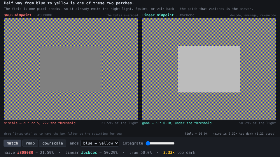
Try blue → yellow: both endpoints are fully saturated, the correct midpoint
is a neutral #bcbcbc, and the naive one is the muddy #808080 that every
two-colour gradient in the world passes through.
Reuse
src/squint.js is a framework-free ES module. No rendering, no timers.
srgbToLinear/linearToSrgb,DECODE(a 256-entry table, since that is the whole domain of a byte),decode8/encode8.light(rgb),lightOfLinear,toLinear,lstar(Y),dLstar(Ya, Yb)— Rec.709 luminance and CIE lightness, so a difference can be stated in units of “can anyone see this”.mix(a, b, t, space),trueLight(a, b, t),rampTable({a, b, stops}),worstDeficit({a, b}),midpoint(a, b)— the claims, computed rather than transcribed.makePattern(kind, {w, h, a, b, period}),ditherRamp,solid,patch— two-valued test images as{data, w, h}, the shapeImageDatatakes.boxDown(img, factor, space),nearestUp,integrate(img, factor),meanLight(img, …)— the filter, in either space, and the one measurement.ENDPOINTS,PATTERNS,SPACES— the vocabulary, so the demo’s selects are generated rather than listed twice.
Gotchas
- The test assumes your display honours sRGB. The checkerboard emits the average of whatever light your panel makes for byte 0 and byte 255, which is physics; that this equals what byte 188 makes is the sRGB transfer function, which is a convention your display either follows or does not. If the patch refuses to vanish on your screen, the demo has told you something true about the screen.
- It also needs real device pixels. The checkerboard is drawn one device
pixel per cell through
putImageData, which ignores the canvas transform for exactly this reason. Browser zoom, a scaled screenshot, or a thumbnail pipeline will resample it — in sRGB — and quietly reproduce the bug it is there to expose. That is whythumb.pngis captured withintegratealready at 4: the field is flat by then and survives being scaled. - The eye is not a box filter. It is a lowpass with a different kernel, it adapts, and it cares about the surround. The box filter is a stand-in that gets the mean light exactly right, and mean light is the only quantity any claim here is made of.
- The dither strip is 8×8 Bayer, so 64 levels. Below
integrate8 its local coverage is quantised and it can sit up to 1.9 points of light off the true t. Raiseintegratebefore trusting it to the last point. - ΔL* on a chromatic pair compares luminance only.
red → greenis scored on Rec.709 Y, which says nothing about the hue shift, and saturated colours look brighter than their luminance (Helmholtz–Kohlrausch). The lightness numbers for the chromatic endpoints are a floor on how wrong the blend is, not the whole of it. boxDownfloors, so a region that is not a multiple of the factor loses its last partial row and column rather than weighting them.- No colour management anywhere. No ICC profile, no wide gamut, no HDR; the bytes are assumed to reach an sRGB display unaltered. That is the pipeline the bug lives in.
- The demo bundles its own copy of
squint.js(self-contained by contract); re-copy after editingsrc/. node scripts/screenshot-demo.mjs [out] [--view=match|ramp|scale] [--ends=] [--integrate=] [--pattern=] [--period=] [--factor=] [--probe=0.5] [--w= --h=]regeneratesthumb.pngandmedia/throughsite/scripts/lib/chromium.mjs, at a device pixel ratio of 1 so the checkerboard stays one pixel wide in the capture.