





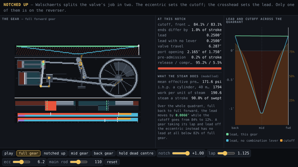
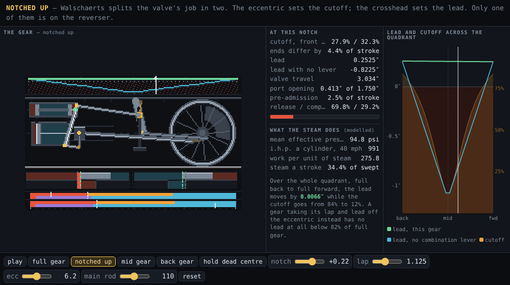
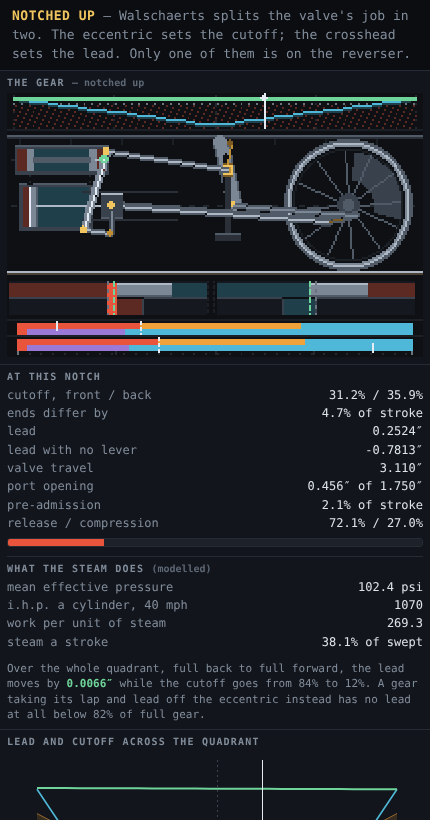
One cylinder of a steam locomotive with outside Walschaerts valve gear, drawn in side elevation at one pixel per inch, which is the only scale at which the rods keep their real proportions to a 63-inch wheel.
A steam engine’s piston is driven both ways, so something has to decide, four times a revolution, which end of the cylinder is on the boiler and which is on the chimney. That something is the valve, and the valve needs a motion about a quarter turn ahead of the piston.
Stephenson’s way, from 1842, was to drive the valve from its own eccentric on the axle, set ahead of the crank by 90° plus an angle of advance that supplied the lap and the lead. Two eccentrics, one for each direction, and a slotted link to blend them.
Walschaerts’ way, from 1844, splits the job in two, and that split is the whole piece:
- One eccentric, at exactly 90°. It swings an expansion link; a die block in the link’s slot is raised or lowered by the reverser, and a radius rod carries whatever the die block gets forward to the top of the combination lever. This is the half that reverses the engine and sets the cutoff, and at mid gear it contributes nothing at all.
- The crosshead, through a short union link, drives the bottom of that same combination lever. The valve rod comes off the lever near the top, so the valve gets a small fixed share of the piston’s own motion. This is the half that supplies lap and lead, and the reverser cannot touch it.
The engine the numbers are off:
| dimension | value |
|---|---|
| cylinder | 21 in bore × 28 in stroke |
| driving wheel | 63 in |
| main rod | 110 in — 3.93 strokes |
| eccentric | 6.20 in throw at exactly 90° |
| eccentric rod | 62.309 in — derived |
| expansion link | 16 in each side of the trunnion, die travel ±8 in |
| radius rod | 62 in, and the slot is struck to that same radius |
| combination lever | radius-rod pin at 41 in, valve pin at 36.965 in — derived |
| lever ratio | 0.90158, so the valve gets 9.84% of the crosshead |
| valve | 1.125 in steam lap, line-and-line exhaust, 1.750 in port |
| head width | 2.875 in = lap + port + exhaust lap |
| design lead | 0.250 in |
Two of those are marked derived because I did not choose them. setValves
does what a fitter does: the valve-pin height is bisected until the dead-centre
opening is the design lead, and the valve rod’s length is set so the two ends
open equally. squareLink solves the eccentric rod for the length that leaves
the link standing at mid-swing at dead centre. Change the lap on the demo’s
slider and all of it is re-derived before the next frame.
Every notch
| reverser | cutoff front | cutoff back | ends differ | lead | valve travel | port opening | m.e.p. | work / steam |
|---|---|---|---|---|---|---|---|---|
| 1.00 | 84.1% | 83.1% | 1.0% | 0.2500 in | 6.287 in | 2.165 in (100%) | 171.6 psi | 190.6 |
| 0.85 | 79.2% | 78.7% | 0.6% | 0.2505 in | 5.549 in | 1.780 in (100%) | 167.5 psi | 196.6 |
| 0.70 | 72.1% | 72.5% | 0.4% | 0.2510 in | 4.841 in | 1.407 in (80%) | 161.1 psi | 205.6 |
| 0.60 | 65.6% | 67.1% | 1.4% | 0.2513 in | 4.393 in | 1.167 in (67%) | 154.7 psi | 214.1 |
| 0.50 | 57.6% | 60.3% | 2.7% | 0.2516 in | 3.972 in | 0.938 in (54%) | 145.4 psi | 225.3 |
| 0.40 | 47.8% | 51.9% | 4.1% | 0.2519 in | 3.587 in | 0.726 in (41%) | 132.3 psi | 240.2 |
| 0.30 | 36.8% | 41.6% | 4.8% | 0.2522 in | 3.252 in | 0.537 in (31%) | 113.8 psi | 258.8 |
| 0.25 | 31.2% | 35.9% | 4.7% | 0.2524 in | 3.110 in | 0.456 in (26%) | 102.4 psi | 269.3 |
| 0.20 | 25.7% | 29.9% | 4.1% | 0.2526 in | 2.987 in | 0.386 in (22%) | 89.5 psi | 279.9 |
| 0.15 | 20.6% | 23.8% | 3.2% | 0.2527 in | 2.888 in | 0.329 in (19%) | 75.1 psi | 288.2 |
| 0.10 | 16.1% | 18.2% | 2.1% | 0.2529 in | 2.815 in | 0.287 in (16%) | 59.9 psi | 291.0 |
| 0.05 | 12.2% | 13.2% | 1.0% | 0.2531 in | 2.771 in | 0.262 in (15%) | 44.4 psi | 281.6 |
| 0.00 | 9.1% | 9.3% | 0.2% | 0.2532 in | 2.756 in | 0.253 in (14%) | 29.2 psi | 246.7 |
The cutoff falls by a factor of nine down that table. The valve travel more than halves. The port opening goes from wide open to a seventh of the port. The mean effective pressure drops to a sixth.
The lead column moves by 0.0032 of an inch.
Across the whole quadrant — full back gear through mid to full forward — it is 0.2500 to 0.2566, a spread of 0.0066 in. Six thousandths. A feeler gauge would struggle to tell you which notch you were in.
The other gear, in the same engine
Take the combination lever’s crosshead input away and make the eccentric supply the lap and the lead instead, the way every gear before Walschaerts did. It needs 29.43° of advance on the eccentric to get a quarter inch of lead in full gear. Then:
| reverser | Walschaerts lead | direct-gear lead | direct-gear travel |
|---|---|---|---|
| 1.00 | 0.2500 in | 0.2500 in | 5.597 in |
| 0.75 | 0.2508 in | −0.0938 in | 4.198 in |
| 0.50 | 0.2516 in | −0.4375 in | 2.799 in |
| 0.25 | 0.2524 in | −0.7813 in | 1.399 in |
| 0.00 | 0.2532 in | −1.1250 in | 0.000 in |
| −0.50 | 0.2549 in | −0.4375 in | 2.799 in |
| −1.00 | 0.2566 in | 0.2500 in | 5.597 in |
A negative lead means the port is still shut when the piston reaches the end of its stroke. Below 81.8% of full gear the direct gear has none at all, and at mid gear the valve has stopped moving entirely, because the only thing moving it was the die block.
That is the chart across the top of the sprite: one flat green line, one deep blue V, and a dark band under the zero line where there is no lead to have.
Why it holds, and it is geometry you can point at
Two facts, and the second is the trick.
The eccentric is at exactly 90°, so at both dead centres its pin is at the top or bottom of its own circle, its horizontal travel is zero, and the expansion link stands square:
| where | expansion link angle | radius-rod pin moves by, full back to full forward |
|---|---|---|
| front dead centre | −1.3 × 10⁻¹⁴ ° | 7.25 × 10⁻³ in |
| back dead centre | −1.3 × 10⁻¹⁴ ° | 7.34 × 10⁻³ in |
And the slot is not straight. It is an arc of radius equal to the length of the radius rod, struck from that rod’s far pin. So when the link stands square, every die position in the slot leaves the radius rod’s far end in the same place — the second column above, seven thousandths of an inch across the entire reverser.
Which means that at the four moments a year’s worth of arguments about lead are actually settled, the reverser is mechanically disconnected from the valve. All that is left holding the valve is the combination lever, and the combination lever is pinned to the crosshead, and the crosshead at dead centre is at the end of its stroke whatever the driver is doing with his right hand.
Those seven thousandths are the whole of the lead’s variation. One arc cannot pass through that pin’s position at both dead centres — it is struck on the mean of the two — and the residual is what the table at the top is made of.
What a wrong eccentric rod costs, and it is less than I expected
I built the eccentric-rod derivation expecting to be able to show the lead falling apart without it. It does not:
| error | eccentric rod | link angle at dead centre | lead over the reverser | spread |
|---|---|---|---|---|
| −2.00 in | 60.309 in | 7.266° | 0.2435 – 0.2500 in | 0.0065 in |
| −1.00 in | 61.309 in | 3.613° | 0.2494 – 0.2500 in | 0.0006 in |
| −0.25 in | 62.059 in | 0.900° | 0.2500 – 0.2527 in | 0.0027 in |
| 0 | 62.309 in | −0.000° | 0.2500 – 0.2532 in | 0.0032 in |
| +0.25 in | 62.559 in | −0.899° | 0.2500 – 0.2536 in | 0.0036 in |
| +1.00 in | 63.309 in | −3.590° | 0.2500 – 0.2537 in | 0.0037 in |
| +2.00 in | 64.309 in | −7.171° | 0.2500 – 0.2518 in | 0.0018 in |
Two inches wrong — three per cent of the rod — doubles the spread to six thousandths and still leaves the lead flatter than anything you could set a valve to. And a rod an inch short is better than the right one, because its link angle at dead centre happens to cancel the slot’s own residual.
So squaring the link is not what makes the lead constant. The lever ratio is what makes the lead constant, and it is a fixed 9.84% of the crosshead no matter what else moves. Squaring the link is what makes the lead come out at the figure you designed for, equally at both ends, which is a different and smaller virtue. I would not have got that from a diagram.
Mid gear is not neutral
valve travel in mid gear: 2.75643 in
twice lap plus lead:      2.75000 in
widest port opening:      0.25323 in
the lead:                 0.25323 in
cutoff front / back:      9.1% / 9.3%
With the die at the trunnion the eccentric’s whole contribution is gone, and the valve is still moving — exactly lap plus lead each way, twice a revolution, driven by nothing but the crosshead. Those two middle lines are the same number because they have to be: in mid gear the widest the port ever opens is the lead. An engine coasting in mid gear is still breathing, 9% of the stroke at a time, which is why you can drift a locomotive on the reverser and why the cylinder cocks are where they are.
The two ends never agree, and the main rod is not most of the reason
The front and back cutoffs differ by as much as 4.8% of the stroke, worst at about a third gear — which is exactly where an engine spends its working life. I assumed that was the main rod’s angularity. It is mostly not:
| main rod | strokes | worst cutoff spread | at reverser |
|---|---|---|---|
| infinite | — | 4.20% | 0.38 |
| 400 in | 14.29 | 4.28% | 0.35 |
| 170 in | 6.07 | 4.51% | 0.30 |
| 140 in | 5.00 | 4.63% | 0.30 |
| 110 in | 3.93 | 4.80% | 0.30 |
| 90 in | 3.21 | 5.00% | 0.28 |
| 70 in | 2.50 | 5.33% | 0.28 |
| 58 in | 2.07 | 5.63% | 0.28 |
An infinitely long main rod — no angularity at all — still leaves 4.20%. Going from a real 3.93-stroke rod to a brutally short 2.07-stroke one only adds another 0.8%. Seven eighths of the disagreement is the gear itself: the union link tilting, the combination lever swinging through 20° rather than sliding, the eccentric rod’s own angularity. Lengthening the main rod is not the fix, and a gear that is square at one end of the cylinder is not square at the other.
What the lap does
| steam lap | cutoff, full gear | cutoff at quarter notch | valve travel | port opening | m.e.p. |
|---|---|---|---|---|---|
| 0.500 in | 96.0% | 61.6% | 6.085 in | 2.696 in | 179.7 psi |
| 0.750 in | 92.1% | 45.9% | 6.135 in | 2.472 in | 177.1 psi |
| 1.000 in | 87.0% | 35.2% | 6.226 in | 2.264 in | 173.8 psi |
| 1.125 in | 84.1% | 31.2% | 6.287 in | 2.165 in | 171.6 psi |
| 1.375 in | 77.8% | 25.1% | 6.436 in | 1.977 in | 166.8 psi |
| 1.750 in | 68.0% | 19.1% | 6.723 in | 1.722 in | 157.9 psi |
| 2.000 in | 61.6% | 16.3% | 6.952 in | 1.567 in | 151.1 psi |
Lap is the shortest cutoff you can reach and the price you pay for it. It also
moves the lever ratio: the valve’s share of the crosshead has to be
(lap + lead) / crank radius, so a 2 in lap needs 16.1% of the crosshead where
1.125 in needs 9.84%. Lap and lead are the only two things that set that
ratio. Sweep the eccentric throw from 4 in to 9 in and the ratio does not move
by a digit, the valve travel nearly doubles, and the lead stays at 0.2500 in
every single time.
The five loops
- full — full forward gear. The link swinging its whole arc, the valve opening the port wide, 84% cutoff.
- notched — the same engine at a quarter notch. The die block has come nearly to the trunnion, the valve barely moves, and the port opens a twenty-sixth of an inch for every thirty-one it does in full gear.
- mid — mid gear. The die is at the trunnion and the valve is still twitching, lap plus lead each way.
- back — full reverse.
- shift — the crank parked on front dead centre while the reverser is pulled from full forward to full back and home. The link stands square the whole time, the die block runs the length of the slot, and the green tick in the port band — the valve’s edge at dead centre — does not move. That loop is the piece.
The frame carries four bands. The chart on top is lead against the reverser, with a gear that has no combination lever drawn beside it. The elevation is one pixel per inch. The band under it is the two steam ports, each magnified ten times in a broken view, because a quarter inch of lead at the elevation’s scale is a quarter of a pixel and the argument would be invisible. The strip at the bottom is the valve events at each end as a share of the stroke — live steam, expansion, release, exhaust, compression — with the piston’s own position riding along it.
What is certain here and what is modelled
Certain. The kinematics. Every position comes out of solving the actual
linkage — the main rod’s angularity, the eccentric rod, the link’s swing, the
curved slot, the union link’s tilt, and a combination lever held by three pins
— with no sinusoid anywhere. The combination lever is a 3×3 Newton solve per
pose (three unknowns: where its bottom pin is and how it leans; three
constraints: the union link’s length, the radius rod’s length, and the valve
pin being on the valve’s axis, which is what makes the mechanism determinate at
all). validateGeometry asserts the linkage residual is under 10⁻⁸ inches at
360 poses across five reverser positions, and it is, at about 10⁻¹⁴.
Modelled. The steam. indicate is the textbook card — boiler pressure
through admission, hyperbolic expansion on the trapped mass, release to back
pressure, hyperbolic compression — with no wiredrawing and no port-area
throttling. It gets the shape right: m.e.p. falling as you notch up while work
per pound of steam rises from 190 to 291 and then turns over as compression
eats the card. Believe the trend. Do not quote the horsepower.
Not modelled. Inertia of the gear, pin clearances and the lost motion that makes a worn gear’s cutoff a range rather than a number, rod whip, and the entire reason a real locomotive’s two cylinders are set 90° apart.
Playing it
The demo is the same module the PNGs are painted with. Pick a loop, drag the notch, or click anywhere on the quadrant chart. Three sliders change the engine itself — steam lap, eccentric throw, main rod — and each one re-commissions the gear from scratch before the next frame: square the link, find which way round it drives, set the valves, strike the slot, repeat until the slot and the lever stop moving each other. Ask for an engine that will not set and it says so and puts the old one back.
Reuse
source/notched-up.mjs is a framework-free ES module. The model and the
drawing are in one file on purpose — the frames in export/ and the demo are
painted by the same code, so they cannot drift.
pose(th, die)— every pin in the gear at one crank angle and one die position.events(die)— the four events at both ends.power(die, mph)— the card.notchCurve()— lead and cutoff across the quadrant, memoised.commission(engine)— re-derives everything after a dimension changes;commission(e, { square: false })leaves a deliberately wrong eccentric rod alone, which is the only way to ask what one costs.directGear(r)— the counterfactual.renderFrame({ r, th })→paintBitmap(ctx, bmp, { scale })for the sprite.scripts/measure.mjsreproduces every table above.source/render.mjsregeneratesexport/,media/,thumb.png, and the demo’s bundled copy of the module.
Gotchas
-
The combination lever has three pins and the valve has one degree of freedom, and that is exactly determinate. Model the valve rod as a link instead and the mechanism gains a degree of freedom and will not solve. The valve rod is a stiff guided stem, so the lever’s valve pin is constrained to the valve’s axis — that third constraint is the mechanism.
-
Which way the reverser drives is a consequence, not a label.
orientGearmeasures it: forward gear is whichever die sign still has the front port admitting just after front dead centre. On this layout it came out the opposite way from the one I assumed, andvalidateGeometrychecks full back gear does negative work on the forward stroke rather than trusting either of us. -
Commissioning has an order, and it bit me.
setValveshas to run once beforeorientGearcan mean anything, because until the valve has been centred and its sign learned, “the front port is open” is not a statement the code can evaluate. Get that backwards and the valves are set in full reverse gear and the lead is a quarter inch in the wrong notch. -
The slot’s arc is struck on the radius rod’s pin, not on the trunnion’s horizontal. My first version centred it
radRodforward of the trunnion, which looks the same on paper and is not: the lead then ran from +0.25 in at full gear to −1.01 in at mid, which is to say the gear turned into a Stephenson. The arc has to pass through where that pin actually sits, about 25 in above the trunnion’s level. -
Moving the main rod moves the cylinder unless you stop it. The crosshead is referred to its own dead centres (
rodRef), so the rod slider changes the shape of the piston’s travel and not where it begins and ends. Without that a 170 in rod walks the crosshead eight inches clear of the combination lever and nothing solves. -
Every event search runs off a cached 720-point sweep rather than its own scan. Bracketing on the sweep and refining by bisection took
events()from about twelve thousand linkage solves to twelve hundred, which is the difference between a quadrant chart and a hung tab. -
The valve is drawn as outside admission — live steam at the two ends of the chest, exhaust through the middle. That is the arrangement in which this layout’s return crank takes the hand it is drawn with. Inside admission reverses the return crank and changes nothing else here.