Everybody has seen this. A car with one wheel on ice, engine screaming, one tyre spinning, and the car not moving. And everybody has heard the same explanation: the torque all goes to the wheel with no grip.
It does not go there. It was always there. It is also, at exactly the same moment, in the wheel that does have grip — the same number, to the newton metre — and that is the whole problem.
The lever with equal arms
A differential is four bevel gears in a box. Two side gears, one splined to each half-shaft, facing each other. Two spider gears on a cross pin, meshing both. A carrier holding the cross pin, bolted to the ring gear, which is the thing the driveshaft turns.
Ride the carrier and it becomes trivial. From there the cross pin is standing still, the spiders are idlers, and an idler between two gears makes them turn opposite ways at the same rate. So in the carrier’s frame the two side gears are always equal and opposite, which rearranges to
ω_left + ω_right = 2 · ω_carrierThat identity is exact. No tooth count appears in it, no torque, no grip, no information about which wheel is where. Whatever one wheel gains the other loses, and the sum is pinned to twice the case. It is the famous half of a differential and it is the half that is taught.
Now turn the same four gears round and look at them as a linkage. The cross pin pushes each spider at one radius. Each spider pushes both side gears at one radius. The two side gears are the same size as each other. There is no arrangement of those contacts in which one side gear comes away with more force than the other, so
T_left = T_right = T_carrier / 2Not “when grip is equal”. Always. A differential is not a device that decides how to divide torque between the wheels. It is a device that cannot divide it. It hands each wheel exactly half and owns no mechanism for doing anything else.
What equal halves cost
A tyre carries μ·N·r before it lets go. On this axle — 1,600 kg, 52% of it
over the driven wheels, a 316 mm rolling radius — that is 4,080 N on each
tyre, and:
| under the tyre | μ | it can hold |
|---|---|---|
| dry tarmac | 0.90 | 1,160 N·m |
| wet tarmac | 0.55 | 709 N·m |
| packed snow | 0.25 | 322 N·m |
| sheet ice | 0.10 | 129 N·m |
| nothing | 0 | 0 |
The moment the worse tyre reaches its number it spins, and its torque stops rising. The other tyre’s torque is the same number, so it stops too. The axle is capped at twice the worse wheel and the better one never finds out what it was capable of.
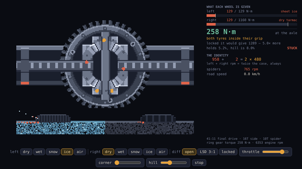
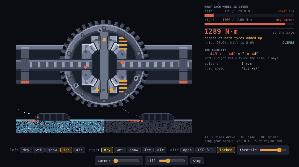
Put one wheel on ice and the other on dry tarmac. First gear at peak torque puts 2,646 N·m on the ring gear. The axle delivers 258. The dry tyre, good for 1,160, is handed 129 — one ninth of itself — and 2,388 N·m goes into spinning a wheel on ice. That is enough thrust to hold the car on a 5.2% slope, so a driveway beats it.
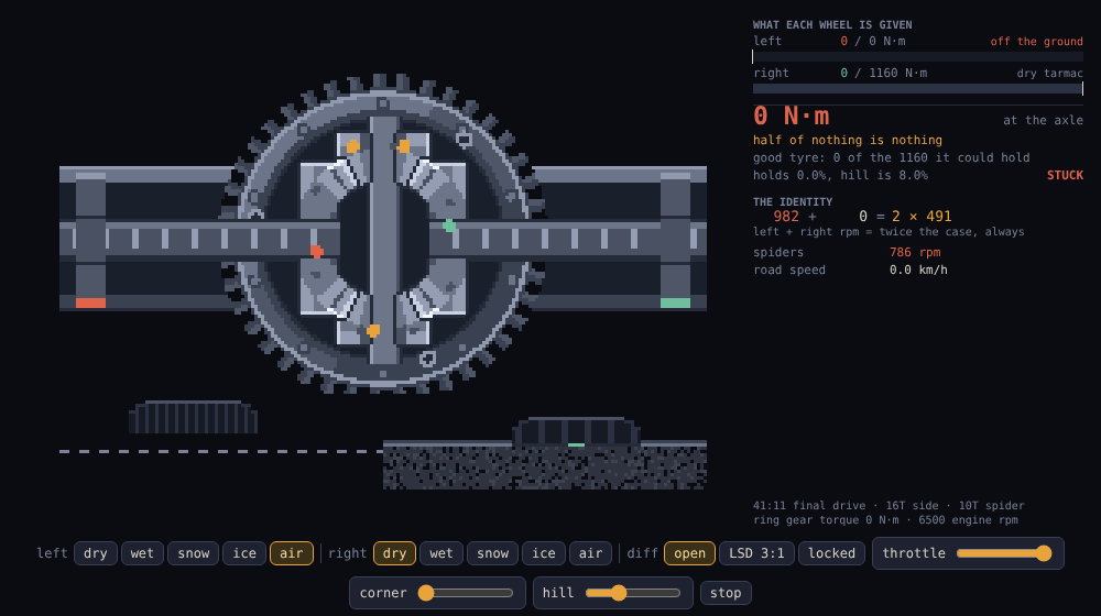
Lift one wheel clear of the ground altogether and the axle delivers zero. Full throttle, a wheel at the rev limiter, every part in the car working exactly as designed, and no thrust at all — because half of nothing is nothing and the other half has to match it.
The half nobody is told
Here is the other side of the same sentence, which almost never gets said: when grip is equal, an open differential costs you nothing.
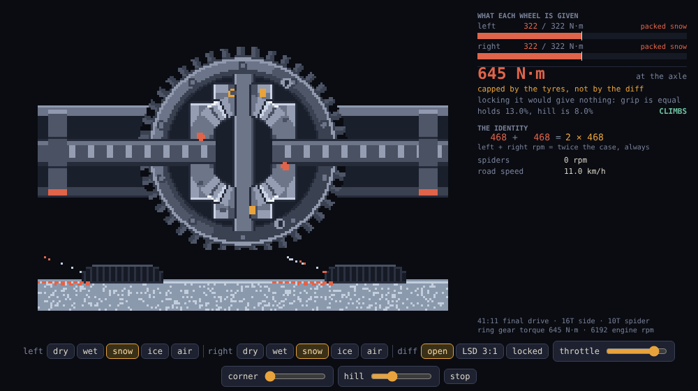
Both wheels on snow, both over their limit, both spinning at the same rate — the axle puts down 645 N·m, and a welded solid axle in the same place would put down 645 N·m too. The spiders do not even turn. An open diff is not a weak axle; it is an axle with one specific failure mode, and that mode is asymmetry. Which is also why the dramatic videos are always of a car with one wheel somewhere different from the other.
The gears nobody thinks about
The spiders are idlers and idlers lead quiet lives. Through a 12 m street corner at 30 km/h the two wheels run at 235.5 and 268.2 rpm, their sum is 503.7, the case is doing 251.8, and the spiders turn at 26.2 rpm — about a turn every two seconds, on plain thrust washers, which is all the duty they were designed for.
Let one wheel go on ice at the same case speed and the spinner takes exactly twice the case while the other wheel sits at zero. The spiders now run at 403 rpm: fifteen times their design duty, under full torque, with the splash of oil they get from a case that is not pumping anything. Spinning a wheel for a minute to get off a sheet of ice is not free, and what it costs is here.
Undoing one word
Every traction device ever bolted to an axle exists to undo the word equal in one sentence.
A limited-slip diff adds internal friction, so the slower shaft can hold back the faster one up to a torque bias ratio. At 3:1 the same ice-and-tarmac axle delivers 516 N·m instead of 258 — still pinned to the worse tyre, but now four times it rather than twice.
A locker bolts the two shafts together and throws the identity away entirely: 1,289 N·m, which is simply the two tyres added up, 5.0× the open diff and good for a 26% slope.
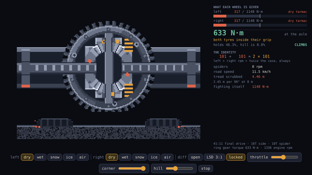
And then it hands you the bill the differential existed to avoid. Locked, both
wheels must turn at one rate along paths of different length. Through 90° at
12 m the outer wheel needs 20.07 m and the inner 17.62, both roll 18.85, and
the 2.45 m of difference comes out of the tread — that is track × angle, with
no other terms in it, and 6.1% slip at each contact patch. Meanwhile the two
tyres are fighting each other with up to 1,160 N·m that the engine never sees
and the driveline has to carry anyway. It is the same tread-sliding bill a
train pays for having no differential at all, which is
Coned from the other end.
Reading the sprite
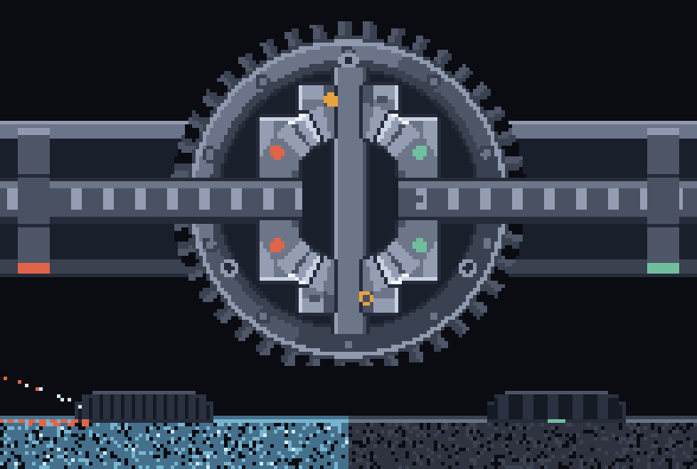
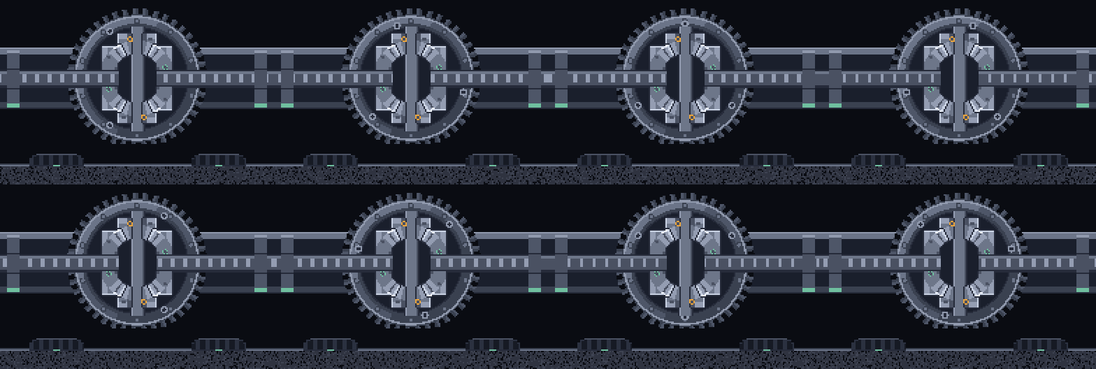
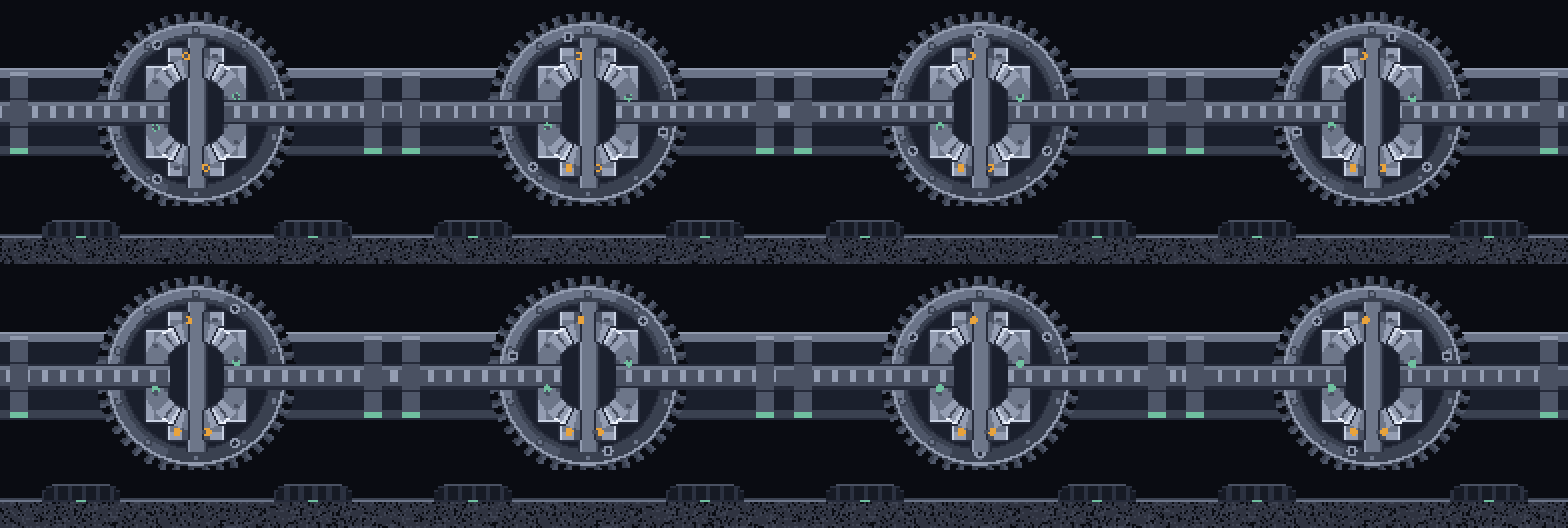
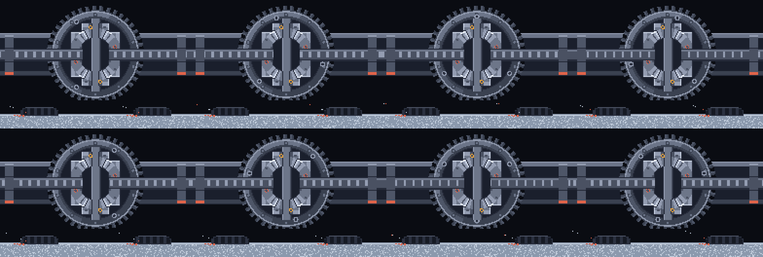
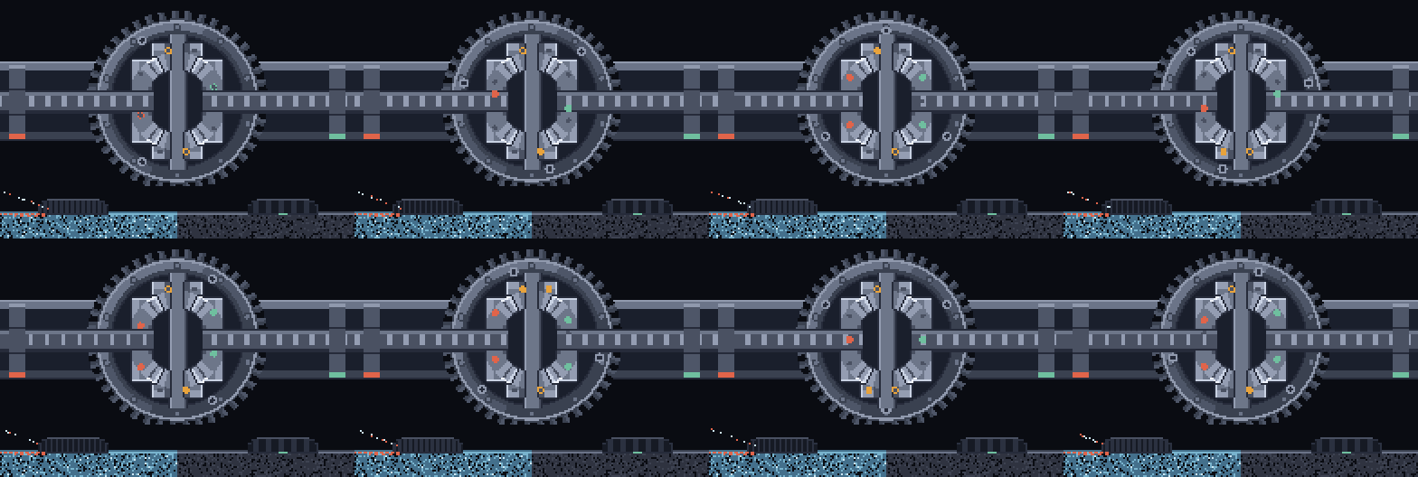
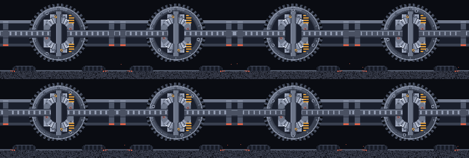
The section plane holds the axle and the cross pin, which means it is bolted to the carrier — so the cross pin stands still in the frame and every gear angle in the picture is measured from the carrier, the frame this thing is simple in. Three witness bolts march round the rim to stand for the carrier’s own rotation; it really turns about the axle, which here is out of the page, so those are an indicator and not a picture. The ring gear’s 41 teeth are real and countable, and 41 is prime on purpose: with an 11-tooth pinion every tooth meets every tooth, so the pair wears in evenly instead of in a pattern. The drive pinion itself is not drawn, because its axis is perpendicular to the page and the 3.73:1 it contributes is a number rather than a shape.
Each gear carries three marks on its back face. On a disc seen edge-on a mark
at angle t sits at r·cos t, so they bob rather than go round — that is the
only honest rotation cue available in a section, and three of them means one is
always worth looking at.
The ground strip is the one thing not to scale: a 316 mm tyre beside a 103 mm ring gear would put the contact patch two frames below this one. But the two things on it that matter are exact — the road scrolls at the car’s speed and the tread blocks scroll at the wheel’s, so a gripping tyre has them moving together and the gap between them is the slip.
The loops:
- straight — both wheels gripping. The spiders never move. A differential going straight is a solid axle carrying four spare gears.
- turn — the 12 m corner. 33 rpm between the wheels, 26 rpm at the spiders, and a sum that does not budge.
- even — both tyres on snow, both over their grip by the same amount. The spiders are still and nothing has been lost.
- split — one wheel on ice, car at a standstill, engine at full chat. The spinner at exactly twice the case, the gripping wheel dead still, and the spiders at fifteen times their corner duty.
- locked — the same corner with the shafts tied together. Equal wheels, both treads scrubbing, the collar drawn in.
The demo
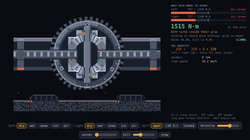
Pick what is under each tyre, pick the differential, and point the car up a
hill. The hill is the part that makes the argument land: on 8% with one wheel
on ice, an open diff leaves the car sitting there with a wheel at 958 rpm and
the other at 2, and the same axle locked climbs it at 41 km/h. The panel keeps
ω_left + ω_right = 2 · ω_carrier on screen throughout, because it holds in
every one of those states, including the ones that look like something has
broken.
The corner slider spends tyre grip on cornering through a proper friction ellipse, so a tight corner slows the car on its own; set the diff to locked with a corner dialled in and the scrub tally counts off real metres of tread as they go.
Reusing it
source/half-each.mjs is the whole thing and it has no dependencies. The
mechanism and the drawing are the same file on purpose: cornerSpeeds,
deliver, axleCeiling, scrub and windUp are the axle, renderFrame is
the picture, and validateGeometry() asserts the identity over a spread of
corners and speeds, checks that equal halves really are equal, that a lifted
wheel delivers nothing, that an open diff gives up nothing on equal grip, and
that the gear cluster physically fits inside the carrier bore. It throws rather
than warns, so a geometry edit that breaks the mechanism cannot reach the site
— the site build imports it.
node source/render.mjs regenerates every PNG here, and writes demo/half-each.js
from the source so the demo can never drift from the exported frames.
node scripts/screenshot-demo.mjs drives the live demo through the interesting
settings, photographs each, and then asserts twenty-two things about what the
simulation actually did — including that the sum of the wheel speeds is twice
the carrier in every state it was put in.